CONTROL KNOB
LOW LIMIT TRIP POINT ADJUSTMENTS
TRIGGER TRIM MODULE TLD 440
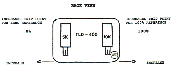
The setting of the Trip Points establishes the linearity of the Control Knob. For the Low Limit channel, use the under load led light located behind face plate (see Installation Manual, Fig. No. 3, TL4043) as an indicator in making the adjustment described below. Turn the Control Knob for the Low Limit towards zero, counter clockwise from 100%. When you reach zero setting or slightly below, the small indicating led should come on. If it does not, turn the 5K pot on the left side of the trimmer module for the Low Limit channel, counter clockwise until the indicator light triggers on, then turn the Control Knob to its full clockwise position, depress the calibrate button and while holding the calibrate button depresses, turn Control Knob, counter clockwise to the 100% mark. The small red led indicator should trigger on. If it does not, turn the 10K pot on the right side of the trimmer module in the clockwise direction with the calibrate button depressed until the red led indicator light triggers on.

In reference to the above drawing, the 5K pot sets the zero Trip Point without pressing the calibrate switch. The 10K pot sets the 100% Trip Point with the calibrate button depressed.
NOTE: A shift in the setting of either pot will cause a shift in the setting of the other pot. You must do this until the gap between the two pots disappears. It will also be necessary to reset the system each time you cause the system to overload.
The method for setting the Trip Points on High Limit are the same, except on the High Limit the overload indicator light on the face plate is used as the indicator.