Operating The Die-Tracker
CHAPTER ONE
"Start Up"
FIVE STEPS TO START USING DIE-TRACKER PLUS
STEP ONE:
ACTIVATE POWER
Once the Die-Tracker plus is installed and correctly calibrated, activate power to the Die-Tracker. Copyright IMCO International Ltd. will first appear on the Alpha/Numeric Display along with the current software version i.e.: 3.60.
After the copyright message, the Die-Tracker will switch to the last page from the factory set up on new systems. After you have set the initial operating limits the Die-Tracker will always switch to the last readings of the last page used in production.
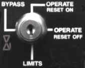
KEY LOCK SELECTOR SWITCH
STEP TWO : SETTING LIMITS
~Default limits have been
set at IMCO. You may use these limits or enter your own limits. If
you choose default limits proceed to step 3~
The "Limits" position is used to enter the limit values or change limit values
and to set the amount of parts to be counted on the Pre-Set Parts Counter.
Turn the Key Lock Selector Switch to the "Limits" position. There are
three limit values and the Pre-Set Parts Counter amount that needs to be
entered: 1) Press Limit; 2) Hi/Low Limits; 3)
Tracking Limits; 4) Pre-Set Parts Counter. The
first "Limit" will appear on the Alpha/Numeric Display, move
the arrow buttons
to increase or decrease the limit values or select the Die-Trackers
pre-programmed limits. Use the
star button to move to the next limit.
Always press the enter button
after a new value has been selected. Pre-Set Parts Counter digits are
moved left to right by pressing the star
button. The limit digit values are changed
by using the arrow button.
Press the enter button
after entering the new numbers of parts to be counted not after each entered
digit.
STEP THREE : BY PASS - SET UP
The "By-Pass" position is used when setting up dies. Turn the Key Lock Selector Switch to the "By-Pass" position. Set up the die in the press that is to be used for production. Make a good part. ~Press limits are always on even in the By-Pass position.~
STEP FOUR : BY PASS - RUN THE PRESS
The adaptive learning "Operate" has two selector switch positions. Operate "reset on" allows the operator to reset overloads/underloads or Operate "reset off" does not allow the operator to reset overloads. underloads. Turn the Key Lock Selector Switch to operate "reset off" or operate "rest on". After the Adaptive Learning Feature samples a part within 8 or 16 strokes, the Die-Tracker plus will calculate and set limits. ~Each time the system is powered up it will keep in memory the last readings.~ Change die after die and never manually set limits again.
STEP FIVE : RELEARN - RECALCULATE LIMITS SET POINTS
1) Press Reset Button - system will relearn or 2) Turn Selector Switch to By-Pass then immediately to any position. System will relearn.
"Limits"
Select the "LIMITS" position on the Key Lock Selector Switch
THE FIRST LIMIT DISPLAY WILL APPEAR:
AUTO HI +08 % (EXAMPLE)
Use arrows to Increase or Decrease Limit Values
![]()
![]() NEXT
LIMIT WILL APPEAR
NEXT
LIMIT WILL APPEAR
PRT LIMIT - 12345678 (EXAMPLE)
Press Star to move each Part Digit from left to right
![]()
![]() NEXT
LIMIT WILL APPEAR
NEXT
LIMIT WILL APPEAR
PRESS LIMIT 107% (EXAMPLE)
Use Arrows to Increase or Decrease Limit Values
![]()
Continue following procedure until all limits
have been entered or changed using the Arrow
Buttons to Increase or Decrease the limits
value, Star Button to move to the next limit
or move digits of the parts count (PRT LIMIT) and Enter
Button to enter or change all limit values.
Refer to Chapter Two for
description of each limit.
CHAPTER TWO
"Understanding The Key Lock Selector Switch"
KEY LOCK SELECTOR SWITCH
The Key Lock Selector Switch has Four Functions
Positions that may be used to operate the Die-Tracker Plus. The Key Lock
Selector Switch can be turned to By-Pass then immediately to any operate
position allowing the Die-Tracker Plus to relearn.
~PRESS LIMITS ARE ALWAYS ON~
TURN KEY LOCK SELECTOR SWITCH TO SELECTED
POSITION
The Four Positions Available for Selection:
BY-PASS - OPERATE (RESET ON) - OPERATE (RESET OFF) - LIMITS
DESCRIPTION:
BY-PASS
This position is used for die
set-up or changing material. It allows the operator to bypass the Die
Limits which have been previously set and disables the Adaptive Learning program
from operating. ~The press
limits are always on even in the By-Pass position~
Relearn
The system will relearn by turning the Key Lock
Selector Switch to BY-PASS then immediately to any operate position.
OPERATE (RESET ON) Adaptive Learning
This position is used to engage the Die-Tracker Plus to operate. This position will allow the overloads, underloads, to be reset. The Adaptive Learning program will take an initial sampling of parts being made within 8 or 16 strokes (other stroke values are available upon request). It will then set the Hi/Low Limits and Tracking Limits with no further assistance from operator or programmer.
OPERATE (RESET OFF) Adaptive Learning
This position is used to engage the Die-Tracker Plus to operate. This position will not allow
the overloads, underloads to be reset. The Adaptive Learning program will take an initial sampling of parts being made within 8 or 16 strokes (other stroke values available upon request). It will then set the Hi/Low Limits with no further assistance from the operator or programmer.LIMITS
Press Limits - Press Capacity Overload Limit. ~Press Limits are always on and cannot be
~Press Limits are always on and cannot be By Passed.~Hi/Low Limits - These limits can be set and left for all dies regardless of their tonnage or can be specifically set for each die. This allows the user to select the percentage above or below the tonnage for a particular job at which the high or low limit will be actuated and allowing for variations in material hardness or thickness in any one coil.
Tracking Limits - The allowable hit to hit repeatable variation in tonnage. If the load changes more than the tracking limits, in a single stroke, the system signals the press to stop. Tracking Limits overlook the gradual changes in load and allow tight tolerances of plus and minus one percent (1%) to be set from one stroke to the next. Missfeeds, broken punches, part ejection failures and material run out can be detected. It is not affected by temperature changes in stock variation. Tracking Limits assure the repeatability of quality parts.
Pre-Set Parts Counter - Counts stroke in which enough tonnage is exerted to make a part. Can be pre-set to automatically stop press after a predetermined amount of parts have been made. When Pre-Set Parts Counter limits have been reached, the Alpha/Numeric Display will show count done.
NOTE: Use arrow buttons, star button and enter button for entering or changing the limits and Pre-Set Parts Counter.
Chapter Three
"Normal Operating Capabilities"
SIX PAGE SELECTIONS
"MAIN DISPLAY" 16 DIGIT ALPHA/NUMERIC DISPLAY

Die-Tracker Plus has six page selections in which the Die-Tracker normally functions:
Tons - Total Percent - Reverse Load - Strokes Per Minute (SPM) - Parts Count- Tracking Limits
While the press is running or not running, the operator can view the load of the press or dies by pushing the arrow buttons up or down. When a overload and/or underload is detected in the die or press, the cause of the condition will readout on the Main Display in exact words and will keep repeating itself until reset. The overloads and underloads can also be viewed on the Load Progression Bar Graphs ( see Chapter Four).
SELECTION OF PAGES AND DESCRIPTION:
PAGES 1 THROUGH 5 SHOWS THE STATUS OF THE SET LIMITS
TOTAL TONS
Total left side and right side readings in tons.
TOTAL PERCENTAverage of the left side percent readings and the right side percent readings displayed in percent.
REVERSE LOAD
Reads the reverse load of the press in percent when performing stripping operations or blanking jobs with snap through loads.
STROKES PER MINUTE
Speed of the press.
PRE-SET PARTS COUNTERCounts strokes in which enough tonnage is exerted to make a part. Can be pre-set to automatically stop the press after a pre-determined amount of parts have been made.
PAGE SIX SHOWS THE HIT TO HIT REPEATABILITY OF THE SET LIMITS
TRACKING LIMITS
The allowable
hit to hit repeatable variation in tonnage. If the load changes more than
the tracking limits, in any single stroke, the system signals the press to stop.
Tracking Limits overlook gradual changes in load and allow tight tolerances of
plus and minus one percent (1%) to be set from one stroke to the next.
Miss feeds, broken punches, part ejection failure and material run out can be
detected. It is not affected by temperature changes or stock variation.
Tracking Limits assure the repeatability of quality parts.
CHAPTER FOUR
"Tonnage Trend - Hi/Low Limits"
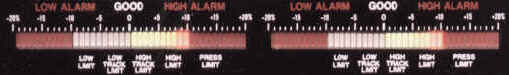
LOAD PROGRESSION BAR GRAPHS
Displays a quick visual reference of the tonnage trend in relation to the Hi and Low Limits that have been set. It shows how close the Die-Load is approaching the learned limits. Ten Led "Load Progression" Segments on the Bar Graphs offer a greater resolution for tonnage interpretation. Each segment between good and bad represents a specific change in load. When press is performing parts at the optimum working condition, the green lights are lit in the center of the bar graphs, any variation will gradually change the color from green to yellow, which can be acceptable to red which would not be acceptable.
HI/LOW LIMITS
Can be set and left for all dies regardless of tonnage or can be specifically set for each die. This allows the operator to select the percentage above or below the tonnage for a particular job at which the Hi or Low Limit will be actuated, allowing for variations in material hardness or thickness in any one coil of material.
CHAPTER FIVE
"Viewing Load Readings"
LOAD READINGS ON FOUR DIGIT DISPLAY

LEFT SIDE AND RIGHT SIDE FOUR DIGIT DISPLAYS
TOTAL TONS
The die load displayed on the Left and Right Side Displays in direct tons. The Total Tonnage of the die load is displayed on the Alpha/Numeric Display.
STROKES PER MINUTE
The die load displayed on the Left and Right Side Displays in direct tons. SPM is displayed on the Alpha/Numeric Display.
PARTS COUNT
The die load displayed on the Left and Right Side Display in direct tons. The Parts Count is displayed on the Alpha/Numeric Display.
REVERSE LOAD
The reverse load displayed on the Left and Right Side Display in percentage of load.
TOTAL PERCENT
The die load is displayed on the Left and Right Side Display in percentage of load. The total percent of the die load is displayed on the Alpha/Numeric Displays.
TRACKING LIMITS
The die load is displayed on the Left and Right Side display in percentage of load.
CHAPTER SIX
"Buttons"
USING BUTTONS TO OPERATE DIE-TRACKER PLUS
The buttons located on the "face Plate" provide
and easy,
practical approach when using the Die-Tracker Plus:
RESET BUTTON - ENTER BUTTON - ARROW BUTTONS - STAR BUTTON
Begin to understand each buttons operating function and the user will quickly bring about the Load Monitoring result they may require.
RESET BUTTON
The main system
RESET BUTTON is used to reset Overloads, Underloads or the Pre-Set Parts Counter values that have been reached.Note: The Key Lock Selector Switch can be turned to the operate position which will allow or not allow the overloads, underloads to be reset. Example: Operate (Reset On) Operate (Reset Off)
ENTER BUTTON
The
ENTER BUTTON must be used when changing Limit values or the Pre-Set Parts Counter values. When entering new Limit values or Pre-Set Parts Counter values, the ENTER BUTTON must be pressed or the new limit or pre-Set Parts Count values will not be accepted.ARROW BUTTONS
A.
The ARROW BUTTONS
are used to select a Page from the SIX PAGE SELECTIONS, Chapter Three, which
shows the status of the limits or hit to hit repeatability. The Page
selected appears on the Alpha/Numeric Display. Pages can be moved forward
or reverse using the ARROW
BUTTONS while
the press is running to review all the load monitoring information which is
occurring.
B.
When the Key Lock Selector Switch is in the Limits position the
ARROW BUTTONS will
increase or decrease the Limit values. Press
ENTER BUTTON when
changing Limit values or the new Limit value information will not be accepted.
Press the STAR BUTTON
(see below) to move to the next
Limit.
STAR
The
STAR BUTTON is used to move to the next Limit selection when the Key Lock Selector Switch has been turned to the Limits position.Press the
STAR BUTTON to move the digits on the Pre-Set Parts Counter from left to right. The digit parts count values are changed by using the ARROW BUTTONS. Press the ENTER BUTTON after the new total number of parts to be counted, not after changing each digit parts count value.PRESS IS NOT RUNNING
1. LOOKING AT THE LIMITS
Press the
STAR BUTTON from any of the SIX PAGE SELECTION to enter the LIMITS. Use ARROW BUTTONS to scroll forward or reverse to review the Limits that have been set. Limits may reviewed, but not changed. The Die-Tracker Plus will time out after 5 seconds and return to the last page selection or return to the last page selection when the press starts up.NOTE:
DIE NUMBER, PART NUMBER, STROKE PER PART AND QC COUNT (QUALITY CONTROL COUNT)
PRESS IS RUNNING
2. LIMITS INFORMATION - IT IS NECESSARY TO BE ON THE PARTS COUNT PAGE
Press the
ARROW BUTTONS to select Page Five PARTS COUNT. The Alpha/Numeric Display will change each time the STAR BUTTON is pressed to show Limit information. This information can be reviewed but not changed. The Die-Tracker Plus will time out after 5 seconds and return to the last page selection.NOTE:
DIE NUMBER, PART NUMBER, STROKE PER PART AND QC COUNT (QUALITY CONTROL COUNT)
CHAPTER SEVEN
"Specifications"
SPECIFICATIONS
EQUIPMENT
SYSTEM ENCLOSURE
13 3/4" ( 349.25 MM ) WIDE
5 3/4" ( 146.049 MM ) HIGH
11 1/2"( 292.099 MM ) DEEP
NEMA 12 SHOCK MOUNTED
POWER
115/220 VOLTS AC
50-60 HZ
RELAY CONTACT RATING
10 AMPS @120 OR 240 VOLTS
SPEED
5 STROKES TO 2500 STROKES PER MINUTE
DISPLAYS
MAIN DISPLAY: 16 DIGIT ALPHA/NUMERIC READOUT .54 HIGH CHARACTERS
TREND BAR GRAPHS: TWO BAR GRAPHS EACH WITH TEN LED LOAD PROGRESSION SEGMENTS
DIGITAL DISPLAYS: TWO DISPLAYS WITH .54 HIGH CHARACTERS
![]()