

LOCATIONS FOR MOUNTING TRANSDUCER BRACKETS
ONE POINT STRAIGHT SIDE PRESSES
COLUMN MOUNTING
IMCO 112G Piezoelectric Transducers on theses
type of machines should be on the columns one 112G front and one 112G rear
opposite of each other on the Columns away from the
keyways. One IMCO 112G Piezoelectric Transducer for each column should
be mounted approximately on a center line
(middle of die
space)between the
bottom of
the ram and the top
of the bed, excluding any
bolster plates, to assure continued optimum output and positive response.
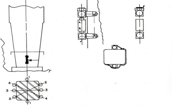
Figure No. 1 & Figure No. 2
PITMAN MOUNTING
For pitman mounting attach two IMCO 112
Piezoelectric Transducers per pitman located 180 degrees from each other and
as close to the directional axis of rotation as possible. Wiring will
be in parallel. Location Z-Z. We do not advise pitman mounting if your pitman is split or it has an
adjustment mechanism in the pitman.
Column Mounting
One Point (One Pitman or Connecting Rod) Straight Side Presses
One
Belfoil Cables each with Two 112G
Piezoelectric Transducers on each cable
NOTE: NEVER - Do not substitute or splice in an alternate type cable. Use only Belden #8451 OR #1503A
![]() -----------35
feet-----------
-----------35
feet-----------![]()
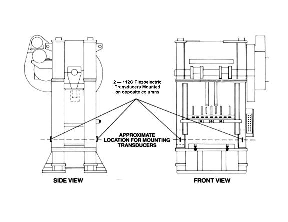
Figure No. 1
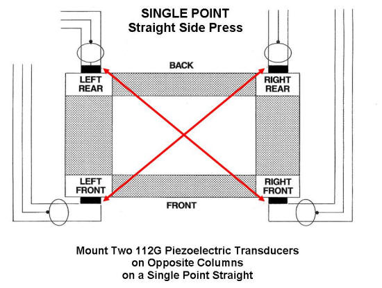
Figure No. 2
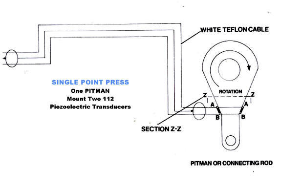
Pitman Mounting
One Point (One Pitman or Connecting Rod) Straight Side Presses
One
Teflon Cable with Two 112
Piezoelectric Transducers between
a 24 Inch (.6 meters)jumper and a 25 Foot (7.50 meters)Tail.
Note: NEVER - Do not substitute or splice in an alternate type cable. Use only Belden #83319
![]() ----24
inches----
----24
inches----![]() -------------25
feet----------
-------------25
feet----------
.6 meters
7.50 meters
MOUNTING TRANSDUCER BRACKETS
Select the IMCO Piezoelectric Transducers mounting locations. Then use the provided self-adhesive templates TLD-3072 to determine the correct mounting distance between the top and bottom bracket for the appropriate IMCO Piezoelectric Transducer. Make sure that in drilling the holes, the piezoelectric transducers will remain parallel to the mounting surface (i.e. columns or pitman's). Use regular capacity 3/8 inch or 1/2 inch power drill; we suggest, if possible, a carbide tipped drill bit, because the outer skin surface of the machine has a tendency to be tempered hardened. Tap each hole using a tapered (do not substitute) pipe tap 1/8 INCH - 27, 11/32 IN. (8.7mm) drill. 7/8 INCH (2CM) deep.
Upon completion, apply a light oil or grease for lubrication and insert both top and bottom brackets; top brackets have the lock nuts and should be mounted on top. Jam the brackets into the frame with an open end wrench so as to get the square part of the bracket body as close as possible to column or frame. Make sure the brackets are tight. Lock nuts should be kissing the frame or column.
TOP AND BOTTOM MOUNTING
BRACKET
WITH PIEZOELECTRIC TRANSDUCER
NOTE:
IMCO
Piezoelectric Transducers are measuring micro strain in
the frame of the press. Brackets should be tightened into press frame as close
as possible to assure maximum transducer signal.
Do not remove set screws when
jamming brackets into Press frame.