

Column Mounting
Column Mounting for C-Frame,
OBI, Gap or Press Brakes
One
Belfoil Cable with Two 112G
Piezoelectric Transducers
NOTE: NEVER - Do not substitute or splice in an alternate type cable. Use only Belden #8451 OR #1503A
![]() -----------35
Feet-----------
-----------35
Feet-----------![]()
10.5 Meters
LOCATIONS FOR MOUNTING TRANSDUCER BRACKETS
OBI - C-FRAME - GAP PRESS OR PRESS BRAKE
Piezoelectric transducers are normally placed one at the back of each frame. (see Fig. No. 1-A and Fig. No. 1-B, Location A). Each is located between mounting brackets positioned approximately on a center line between the top and bottom of the gap, excluding any bolster plates. This location permits individual readout of peak load on each frame and is the preferred mounting location.
Figure No. 1-A
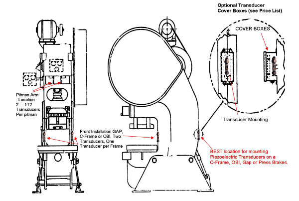
Figure No. 1-B
If for any reason
the IMCO 112G Piezoelectric Transducers cannot be located on the back of each
frame, then they can be mounted on the pitman using IMCO 112 Piezoelectric
Transducer. Two IMCO 112 Piezoelectric Transducers per pitman mounting
connected in parallel will provide only a single channel of readout. Make sure
you have a pitman piezoelectric transducer cable for this mounting choice.
We do not recommend mounting piezoelectric transducers on the sides of this type
of press because you will be picking up bending.
Note:
If pitman mounted, mounting will be the same as straight side press.
MOUNTING TRANSDUCER BRACKETS
Select the IMCO piezoelectric transducers mounting locations. Then use the provided self-adhesive templates TLD-3072 to determine the correct mounting distance between the top and bottom bracket for the appropriate IMCO piezoelectric transducer. Make sure that in drilling the holes, the piezoelectric transducers will remain parallel to the mounting surface (i.e. columns or pitman's). Use regular capacity 3/8 inch or 1/2 inch power drill; we suggest, if possible, a carbide tipped drill bit, because the outer skin surface of the machine has a tendency to be tempered hardened. Tap each hole using a tapered (do not substitute) pipe tap 1/8 INCH - 27, 11/32 IN. (8.7mm) drill. 7/8 INCH (2CM) deep.
Upon completion, apply a light oil or grease for lubrication and insert both top and bottom brackets; top brackets have the lock nuts and should be mounted on top. Jam the brackets into the frame with an open end wrench so as to get the square part of the bracket body as close as possible to column or frame. Make sure the brackets are tight. Lock nuts should be kissing the frame or column.
TOP AND BOTTOM MOUNTING
BRACKET
WITH PIEZOELECTRIC TRANSDUCER
NOTE:
IMCO
Piezoelectric Transducers are measuring micro strain in
the frame of the press. Brackets should be tightened into press frame as close
as possible to assure maximum transducer signal.
Do not remove set screws when
jamming brackets into Press frame.